Introduction:
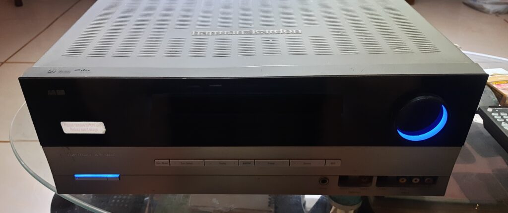
Apart from my Harman Kardon AVR 132 home theatre amplifier that does not turn on and only on standby mode, and another one that I bought on Carousell, I bought another similar defective AVR132 that I found on Facebook Marketplace to see if I can fix it which I did.
Figure 3.0: Harman Kardon blue light on, no display, no power

There are three cases covered in this series of three posts. This post covers Case 3.
- Case 1: Amber light or standby light on, no display, no blue light, no power.
- Case 2: Powering on, with display but system goes in protect mode seconds after turning on.
- Case 3: System-on blue light indicator turning on and off, no display, no audio output.
Disclaimer:
Working on electronic devices such as audio amplifiers pose a risk for electric shock. Safety first before anything else. Wear appropriate personal safety equipment (PPE), at least a pair of rubber gloves and rubber shoes before working.
It is advisable for the DIY enthusiast to know at least basic electronics/electrical concepts before attempting to fix and/or refurbish electronic devices. Otherwise, do some due diligence first about the subject or get the service of your favorite electronics technician to do the job for you and use this blog article as reference if necessary.
Any accident, loss of life or damage to property that may arise from the carelessness of the DIY enthusiast when working with a similar project is not the responsibility of the author.
Case 3: System-on blue light indicator turning on and off, no display, no audio output.
This unit is the one I purchased on Facebook marketplace to see if I can fix it or if not, use it as source of spare parts for the two other units. To my surprise, it turned out that Case 3 is the easiest to fix compared to Case 1 and Case 2.
Section 1: Understanding the problem and troubleshooting steps.
Since the units System-on blue light indicator is turning on and off, the audio input board switching functions are probably working well except that the power relay is not getting triggered to engage. So, I narrowed the trouble on the power relay circuitry.
Troubleshooting Case 3 is simply straight forward with minimal work and complexity:
- Remove all side and back screw of the top cover to remove it. Remove all screws at the back of the unit to detach the video audio input board, tuner board, optical/coaxial board, audio input board, and main power amplifier board from the chassis.
- Disconnect all connectors to video audio input board, tuner board and, and audio input board and take the three boards out to access the main power amp board.
- Remove all screws attaching the heat sink and main power amp board to the bottom chassis. Most screws are accessible but one is obscured by the audio input board that’s why it needs to be removed.
- After removing the hidden screw under the audio input board, re-install the audio input board and re-connect connectors CN10, CN18, CN72. These connectors carry the supply and the signals for power on/off functions. Leave other connectors disconnected.
- Tilt the main power amp board with the re-installed audio input board vertically to the left side to access the circuitry at the back side of the board. Make sure that exposed component terminals do not touch the chassis to avoid short circuit possibilities.
Section 2: Troubleshooting and fixing the problem
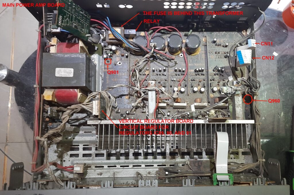
- Plug the power cord to the mains and press the standby switch. Check for +12 ~ 15 V DC voltage at the terminals CN20 on the audio input board. If it is present then proceed to the next step. Otherwise, replace voltage regulator IC90. IC90 can be found at the vertical inserted regulator board (refer to Figure 3.1).
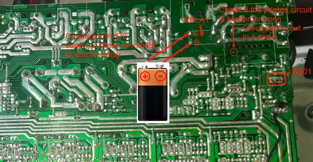
- Locate the relay terminals near the top right corner of the main power amp circuit board. Connect a 9V battery to the relay terminals to check if the relay engages. Connect the terminals as shown in Figure 3.2. If the relay is good, you should hear a clicking sound. Proceed to step 2. If no clicking sound heard, replace the relay and check if it engages when pressing the power button or using a remote control. If it powers on, then the problem is solved.
- Check for +12V voltage at the relay terminal A using a multimeter. Place the negative probe at the speaker ground (black) terminal and positive probe at terminal A of the relay. If +12V is present then proceed to the next step, otherwise, check the printed circuit connected to terminal A of the relay for corrosion and continuity to R911 (refer to Figure 3.2). The printed circuit might be broken as in the case of my third AVR. Clean the corroded part to expose the copper printed circuit then solder the cracked or broken part together. Case 3 was solved up to this point. The image in Figure 3.2 is taken from Case 2 and does not show the soldered broken printed circuit.
- If the problem is not solved in your case, check for +12V voltage at the relay terminal A. Remove the negative probe of the multimeter and place at relay terminal B and positive probe at relay terminal A. If no +12V reading, the printed circuit that connect terminal B of the relay to the switching transistor Q901 circuit might be open or broken due to corrosion (see Figure 3.2). If this is the case, clean the corroded part to expose the copper printed circuit then solder the cracked or broken part together.
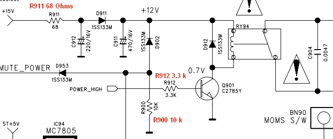
- The unit should already power on with the display on however if it’s not the case, check the switching transistor Q901 and R912. Q901 receives the power_high signal voltage in its base and acts as a switch to conduct electricity from relay terminal B through its collector to emitter that is connected to ground to engage the relay. Replace if either or both are defective.
Figure 3.1: Main Power Amplifier Board

Figure 3.2: Relay Circuit Diagram

Figure 3.3: Relay Circuit Diagram

Section 3: Testing and Validation
Similar to Cases 1 and 2, the amplifier should be tested thoroughly to ensure its functionality and performance. Put every board and screws in its place but don’t put back the cover yet. Connect the speakers and inputs that you use then test all functions of the unit. Watch a movie or two while keeping the amp open to check for any unexpected issues such as overheating of the heatsink, burning smell, and/or smoke from burning parts. If there are no issues, it’s time to re-install the tuner board, video board though not used anymore and re-install the cover.
I tested Case 3 using digital coaxial output from my TV connected to the digital coaxial input of the AVR, and analog source from my Android phone to analog inputs of the AVR and all works fine. There is a standing issue on the subwoofer output but can be remedied by connecting a short wire from the Front Left or Front Right speaker terminal to the LFE input terminal of the subwoofer.
Case 3 Summary:
Initial Issue:
- I bought a unit on Facebook Marketplace to either fix or use for spare parts. Surprisingly, it was the easiest to fix compared to my other units.
2. Understanding the problem and troubleshooting steps:
- The blue light indicator was turning on and off, indicating the power relay circuitry was likely the issue.
- I removed the screws and disconnected the boards to access the main power amp board.
- After re-installing the audio input board, I accessed the back of the main power amp board for troubleshooting.
3. Troubleshooting and fixing the problem:
- I checked for the correct voltage and tested the relay with a 9V battery.
- If the relay didn’t engage, I would replace it and check for +12V at the relay terminals.
- I cleaned and soldered any corroded or broken circuits.
- If issues persisted, I would inspect the switching transistor Q901 and R912 and replace them if needed.
4. Testing and validation:
- I thoroughly tested the amplifier with the boards reassembled but the cover off.
- I watched movies to check for issues like overheating or burning smells.
- After confirming no issues, I reinstalled all boards and the cover.
- Testing with digital and analog sources showed everything worked fine, except for a subwoofer issue which I fixed with a short wire connection.
Conclusion:
Fully fixed the unit with all functions working including remote control except for subwoofer out signal not present. Can be remedied by connecting a short wire from the Front Left or Front Right speaker terminal to the LFE input terminal of the subwoofer.
Exploring similar fixing or repurposing projects can be a rewarding and innovative way to deal with electronic equipment issues. By diving into DIY repairs, you not only breathe new life into seemingly unusable devices but also unleash your creativity and problem-solving skills. Projects like these offer a unique opportunity to learn about electronics, understand intricate circuits, and discover the satisfaction of fixing something with your own hands. Whether you’re repurposing an old amplifier or tackling another electronic challenge, the journey is filled with learning, innovation, and the joy of turning the old into something functional and new. Embrace the adventure, and you might be surprised by what you can achieve!
Product References:
Soldering Tools Set:
Buy it here: https://s.shopee.ph/VlrChq5qW 
Hot Air Gun Soldering :
Buy it here: https://s.shopee.ph/3AmcO7oo7c 
Digital Multimeter:
Buy it here: https://s.shopee.ph/B90qN98FM 
Analog Multimeter:
Buy it here: https://s.shopee.ph/2VWvd43LkB 
Buy it here: https://s.shopee.ph/1B29ytdgUS 