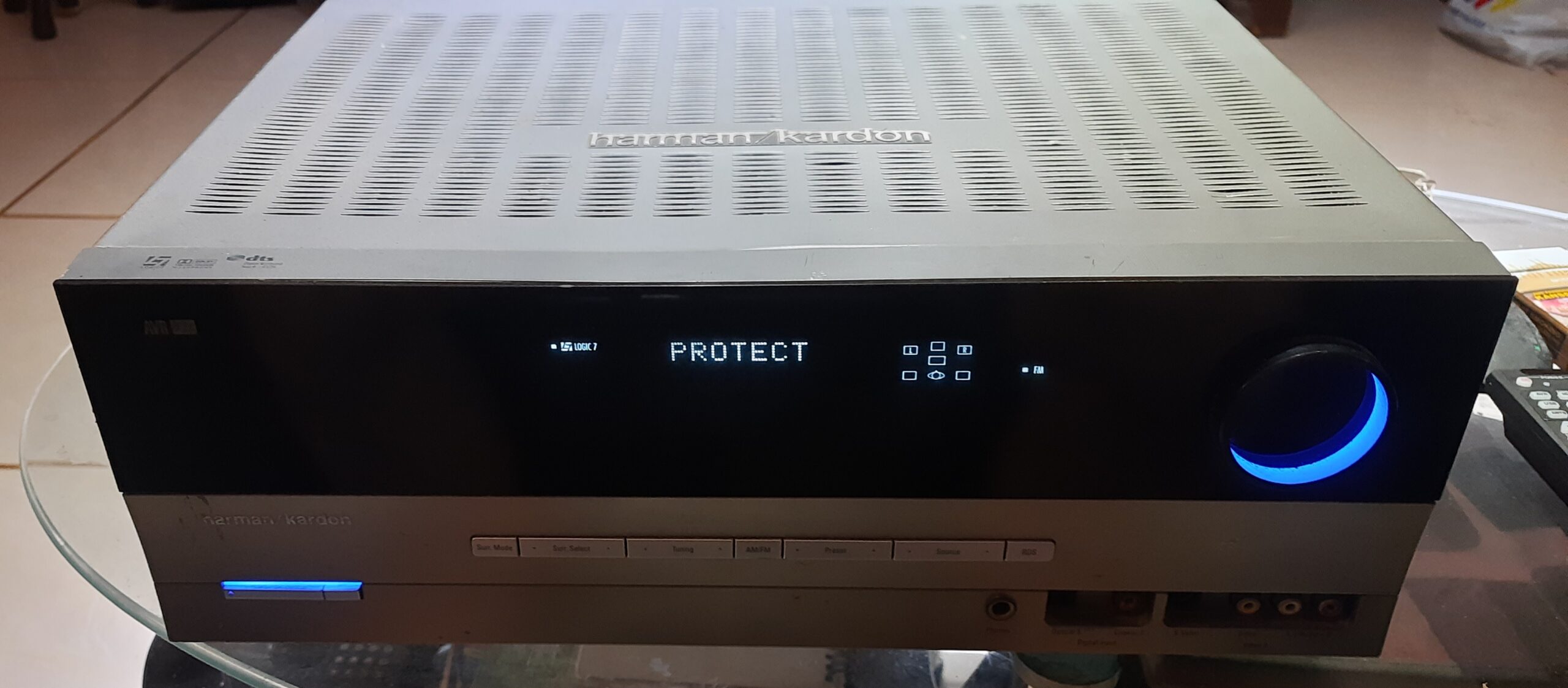
Harman Kardon AVR 132 goes on Protect Mode seconds after power on.
Introduction:
Apart from the other two Harman Kardon AVRs that I fixed, I bought another similar defective AVR132 that I found on Carousell to see if I can fix it as well.
Figure 2.1: Harman Kardon AVR 132 Protect Mode
 |
There are three cases covered in this series of three posts. This post covers Case 2.
- Case 1: Amber light or standby light on, no display, no blue light, no power.
- Case 2: Powering on, with display but system goes in protect mode seconds after turning on.
- Case 3: System-on blue light indicator turning on and off, no display, no audio output.
Disclaimer:
Working on electronic devices such as audio amplifiers pose a risk for electric shock. Safety first before anything else. Wear appropriate personal safety equipment (PPE), at least a pair of rubber gloves and rubber shoes before working.
It is advisable for the DIY enthusiast to know at least basic electronics/electrical concepts before attempting to fix and/or refurbish electronic devices. Otherwise, do some due diligence first about the subject or get the service of your favorite electronics technician to do the job for you and use this blog article as reference if necessary.
Any accident, loss of life or damage to property that may arise from the carelessness of the DIY enthusiast when working with a similar project is not the responsibility of the author.
Case 2: Powering on, with display but system goes in protect mode seconds after turning on.
This is the case for the one that I purchased online in carousell.ph. The amp immediately powers down and goes in protect mode after powering on. This case is relatively simpler to solve and not so laborious compared to Case 1.
Section 1: Understanding Protect Mode and Troubleshooting Procedures
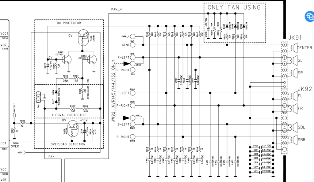
Typical to most home theatre AVR amplifier regardless of brand name, protect mode is triggered during an overload when the speaker terminals are shorted, excessive heating of the heatsink of the main power amp transistors, and when DC voltage is detected in the positive speaker terminal output. DC voltage detection is handled by a DC Protector circuit as shown in figure 9 below. Note that the DC voltage reading on any of the positive speaker terminals for all channels should be zero volts (0V). This can easily be checked using a multimeter set to measure DC voltage at 50V. If no multimeter or tester is available, a DC hum can be heard momentarily after turning the unit on. If it’s too bad, the unit goes on PROTECT MODE and eventually shuts down.
Figure 2.2: DC Protector Schematic Diagram
We need the same set of and set of procedures for opening the top cover of the unit as previously discussed in Case 1. Additional tools hot air gun desoldering station, soldering flux paste, and desoldering braid.
| Figure 2.3: Soldering Tools |

Section 2: Troubleshooting and fixing the problem
Reference Images:
Figure 2.4: Op-amp Circuit Block
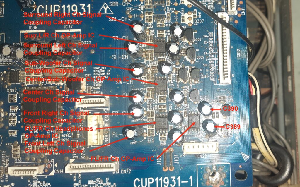
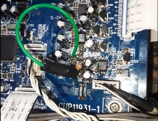
Figure 2.5: Op-amp Circuit Bypass Resistor
The following are the steps that I did for Case 2.
- Measured the presence of DC voltage on all of the 5 speaker terminals and read 12V DC on the Front Left and Front Right Speaker terminals.
- Measured the presence of DC voltage on the headphone jack by plugging in a stereo PL55 jack and also read the presence of DC voltage.
- Traced the source of the DC voltage and found out that it comes from the operational amps (op-amps) for headphones and for the Front Left and Front Right Channels.
- Disconnect CN12 from the main power amp board to isolate the op-amps circuit from the main board and confirm DC voltage on the pins for Front Left and Front Right.
- Tried switching the amp on and guess what? Protect mode didn’t kick in. All switching functions e.g. changing inputs, surround modes, volume, remote control functions seem to work as shown on the display.
- Disconnected the power cable from the mains, removed the audio input board to access it’s back and removed the Front Left and Front Right signal coupling capacitors C389 and C390 respectively using a soldering rod.
- Re-installed the audio input board, re-connected CN12 to the main power amp board, connected analog and digital/coaxial inputs and speakers for Surround L/R, and Center channels one at a time. Power the amp on and tested the audio output from the Center speaker first. No sound came out from the speakers similarly with the Surround L/R speakers. But then, touching the top of C283, the signal coupling capacitor for Center Channel op-amp produces a loud hum on the speaker. So, I suspected that there’s probably a problem with the analog/digital/coaxial input signal processing controlled by IC20 (refer to Figure 2).
- Connected the test signal to the center channel input of the 6-channel Direct Input terminals and got good audio output. Now, at least we know that the real culprits causing the DC voltage at the speakers are op-amps IC21 and IC25 that have shorts in the internal circuitry. But then, there’s another problem with the analog/digital/coaxial input signal processing.
- Removed IC21 and IC25 using a hot air gun desoldering station (Figure 13). Took the spare parts from digital signal op-amps on the audio input board of my old AVR and installed the ICs in place of the shorted IC21 and IC25. I didn’t take a photo or video about the process but you can search online tutorials on how to do it.
- Retested the sounds using 6-channel Direct Input and noted that all channels have audio output except for the Front Right Channel. But touching the signal coupling capacitor C372 to the FL/FR op-amp IC21 creates a loud hum. Tried shorting or bypassing the signal coupling SMD (Surface Mounted Device) micro-resistor R282 to the input pin 1 of the R/L op-amp IC21 then voila, the right channel outputs the audio signal louder than the other channels. What I did for a temporary solution is to bypass the failing SMD resistor using a through-hole/old design resistor with a serial wire connection (green wire) as shown in figure 12. I got a spare resistor on another defective board but didn’t attempt to extract the tiny thing to replace the defective one. The micro-resistor, a 5.1 k Ohms SMD reads good when tested using a muti-meter. You guess it right if you think that SMD resistor is open or intermittently opens when power is present.
There is still another standing problem. Most input sources work on Stereo/Surround Off mode and do not work while Logic 7, DSP, Dolby, and DTS surround modes are on though, except for 6-channels Direct Input. These input mode bypasses the DSP, Dolby, and DTS surround processing and the inputs are directly connected to the op-amps, the pre-amp, then the main power amp similar. I suspect that there is something wrong with the surround processor IC20.
The dedicated +7V and -7V DC supply to IC20 are present. I tried doing a hard reset by pressing the Surround button while the unit is in standby mode. I tried reflowing the solders of all of the ICs on the audio input board by applying heat using the hot air gun but didn’t solve the problem. IC20 can still process switching signals from any of the analog and digital input sources but unable to process surround modes and can only send the signal direct to the amplifier block in Stereo/Surround Off mode for most input signals and in 6-channel direct modes. Noted that IC20 barely gets warm while power is on that can be a symptom of open connections in its internal circuitry. I searched the internet for solutions to a similar problem but found none.
Section 3: Testing and Validation
Similar to Case1, it is important to test the amplifier to ensure its functionality and performance. For this we need a 6-channels audio sources to test that all amp channels are working. Connect 6-channel signal outputs from a DVD player with 6-channels surround output or a 6-channel surround decoder output to the 6-Ch Direct input of the amplifier. Be sure to connect an audio source to the input of the 6-channels surround decoder. Connect the all the speakers and the subwoofer as usual. The remote control of my old AVR was lost or misplaced somewhere in the house so I bought a new one for HK AVR700 online. The remote control is compatible and works for most functions though the only useful functions for this case are power on/off, volume control, speaker level adjustment, mute, and dim.
Figure2.6: Compatible Remote Control

Power on and test the sound, turning the new volume controls up or down. Watch a movie or two while keeping the amp open to check for any unexpected issues such as overheating of the heatsink, burning smell, and/or smoke from burning parts. If there are no issues, it’s time to re-install the tuner board, video board though not used anymore and re-install the cover.
Case 2 Summary:
Wrapping it all up for Case 2:
1. Initial Issue:
- I purchased an amplifier online that powers on but quickly goes into protect mode.
2. Understanding Protect Mode:
- Protect mode can be triggered by:
- Shorted speaker terminals.
- Excessive heating.
- DC voltage in the speaker terminal output.
3. Detecting the Problem:
- Measured 12V DC on the Front Left and Front Right speaker terminals.
- Traced the issue to the operational amps (op-amps) for these channels.
4. Initial Troubleshooting:
- Disconnected the op-amps circuit, stopping protect mode from activating.
- Removed the signal coupling capacitors C389 and C390 to isolate the problem.
- Test signal touching signal input pins of CN12 to the pre-amp and confirmed humming sound output.
- Confirmed op-amps IC21 and IC25 were causing the DC voltage issue.
- Replaced the faulty op-amps with spare parts.
5. Reinstallation and Testing:
- Reinstalled the board and reconnected inputs and speakers.
- Tested audio output:
- Good sound from Left, Center and Surround speakers but no sound from Right speaker.
- Touching a signal coupling capacitor produced a loud hum on Right speaker.
6. Further Troubleshooting:
- Identified a problem with input signal processing controlled by IC20.
- No audio output on Right Channel caused by an intermittently open SMD resistor connected the input pin of IC21.
7. Temporary Fix:
- Bypassed a faulty 5.1 kΩ SMD resistor by connecting a parallel resistor to fix the Front Right channel temporarily.
8. Remaining Issues:
- Input sources only worked in Stereo/Surround Off mode, not in surround modes like Logic 7, DSP, Dolby, or DTS.
- Suspected problem with the surround processor IC20:
- Power supply to IC20 was functioning.
- Hard reset and reflowing solders didn’t fix the issue.
- IC20 barely warmed up, indicating possible internal connection problems.
- Unable to find online solutions for this problem.
9. Finally, I tested and validated the repurposed amplifier:
- Connect a 6-channel audio source to 6-Ch Direct input of the amplifier.
- Test sound output and adjust volume controls.
- Monitor for any unexpected issues like overheating or burning smell.
- If everything works, reassemble the unit and enjoy the new functionality.
Conclusion:
Though I was not able to fully fix the unit with all functions, the 6-channel input works well and has attained the minimum viable product for the purpose of watching movies and listening to music in 5.1 surround audio. Remote control functions work as well for volume control, power on/off, and setting up speaker volume levels. Compared to Case 1, this unit has better functionality.
Exploring similar fixing or repurposing projects can be a rewarding and innovative way to deal with electronic equipment issues. By diving into DIY repairs, you not only breathe new life into seemingly unusable devices but also unleash your creativity and problem-solving skills. Projects like these offer a unique opportunity to learn about electronics, understand intricate circuits, and discover the satisfaction of fixing something with your own hands. Whether you’re repurposing an old amplifier or tackling another electronic challenge, the journey is filled with learning, innovation, and the joy of turning the old into something functional and new. Embrace the adventure, and you might be surprised by what you can achieve!
Product References:
I’ll get a small commission if you buy the products from my links.
Digital 5.1 Audio Decoder Dts/Ac-3 Optical To 5.1-Channel RCA Analog Converter:
Buy it here: https://s.shopee.ph/7fF1j8uSBG 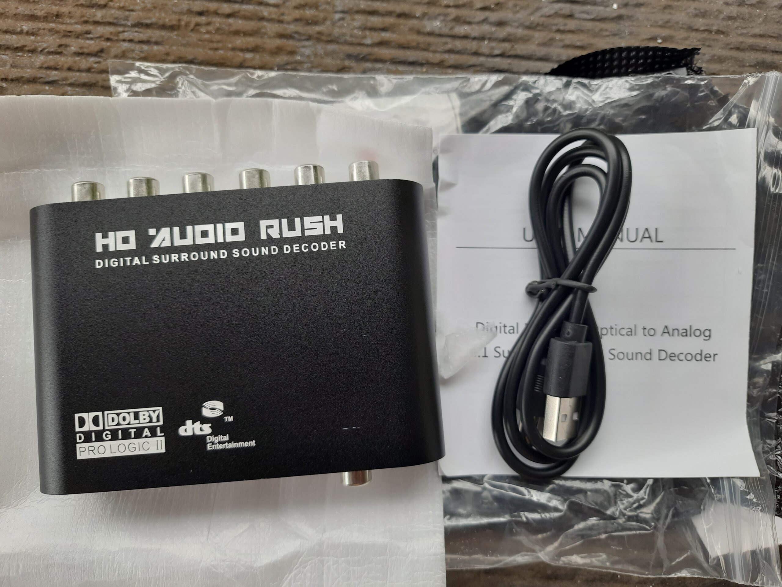
Soldering Tools Set:
Buy it here: https://s.shopee.ph/VlrChq5qW 
Hot Air Gun Soldering :
Buy it here: https://s.shopee.ph/3AmcO7oo7c 
RCA Cable Male to Male:
Buy it here: https://s.shopee.ph/40LjNsONfz 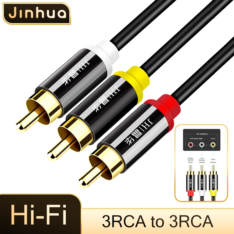
RCA Input Ports Female:
Buy it here: https://s.shopee.ph/A9wMjTgq3S 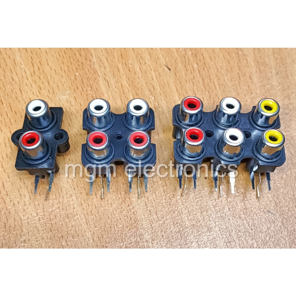
Digital Multimeter:
Buy it here: https://s.shopee.ph/B90qN98FM 
Analog Multimeter:
Buy it here: https://s.shopee.ph/2VWvd43LkB 