Struggling to fix a defective Harman Kardon AVR that won’t turn on, keeps going into protect mode, or powers up without display or sound? Dive in to uncover valuable insights and solutions to get your home theatre amplifier back in action!
Introduction:
I have a Harman Kardon AVR 132 home theatre amplifier that does not turn on and only on standby mode. The amber light is on but the blue light system-on indicator does not turn on. The relay does not engage and there’s no clicking sound when pressing the power button. I bought the unit along with JBL E series speakers; subwoofer, front tower speaker/baffles, center speaker, and book shelf surround speakers in the year 2007 when I was working in Dubai, UAE. The amp worked for 7 years till 2014 then stopped working due to moisture on the audio input board. I initially diagnosed the problem with the audio input board and tried sending it to the vendor in Dubai to see if it can be fixed or if not, replace the whole board with a new one. Unfortunately, the vendor said that the unit is old and production of the audio input board is discontinued. I also searched the internet for a spare board but didn’t find any. So, I thought that the unit is hopeless and kept it for years until this year, when I had the spare time to explore possible solutions to at least make the main pre-amp and main amplifier work as a dedicated amp or booster amp without any other functions.
The problem with my HK AVR 132 re-ignited and rekindled my interest in electronics and embarked on a self-challenge to fix the amp to pass idle time and to re-learn the old trade and learn about micro-electronics that barely exist yet during my youth. I searched the internet and found some ideas and inspiration watching videos posted by electronics technicians and DIY enthusiasts on YouTube about solutions to similar problems. I used ChatGPT to get insights and deeper understanding on how biasing transistors and switching circuits work and information about certain parts of the circuit. I bought two other similar defective AVR132 that I found on Facebook Marketplace and the other on Carousell to see if I can fix both as well.
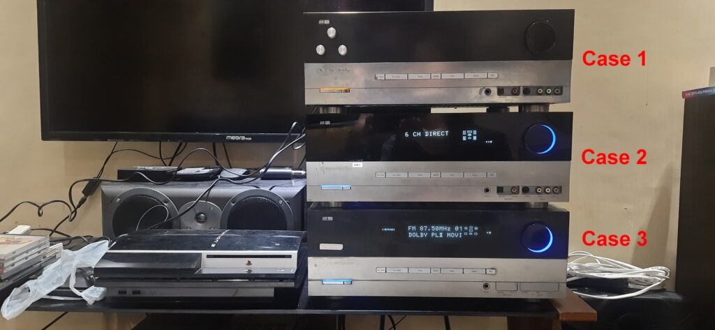
There are three cases covered in this series of blog posts. I split the topics into three cases for the readers to save time and only read the appropriate post that applies to the case of their AVR. This post coverse Case 1.
- Case 1: Amber light or standby light on, no display, no blue light, no power.
- Case 2: Powering on, with display but system goes in protect mode seconds after turning on.
- Case 3: System-on blue light indicator turning on and off, no display, no audio output.
Disclaimer:
Working on electronic devices such as audio amplifiers pose a risk for electric shock. Safety first before anything else. Wear appropriate personal safety equipment (PPE), at least a pair of rubber gloves and rubber shoes before working.
It is advisable for the DIY enthusiast to know at least basic electronics/electrical concepts before attempting to fix and/or refurbish electronic devices. Otherwise, do some due diligence first about the subject or get the service of your favorite electronics technician to do the job for you and use this blog article as reference if necessary.
Any accident, loss of life or damage to property that may arise from the carelessness of the DIY enthusiast when working with a similar project is not my responsibility.
Case 1: Amber light or standby light on, no display, no blue light, no power.
Section 1: Understanding the Problem and Troubleshooting Procedures
Get the following tools handy before starting the activity: soldering rod, soldering lead, tweezer, long nose plier, wire cutter/nipper, multimeter, and a phillips screw driver.
The following are the steps that I did for Case 1. Some of the steps can be common and can be applied to Case 2 and Case 3. Refer to reference images for the location of parts.
Figure 1.1: Main Power Amplifier Circuit Board – Top View
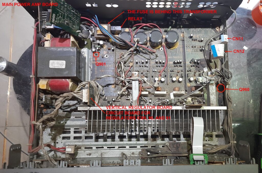
Figure 1.2: Audio input board – Top View
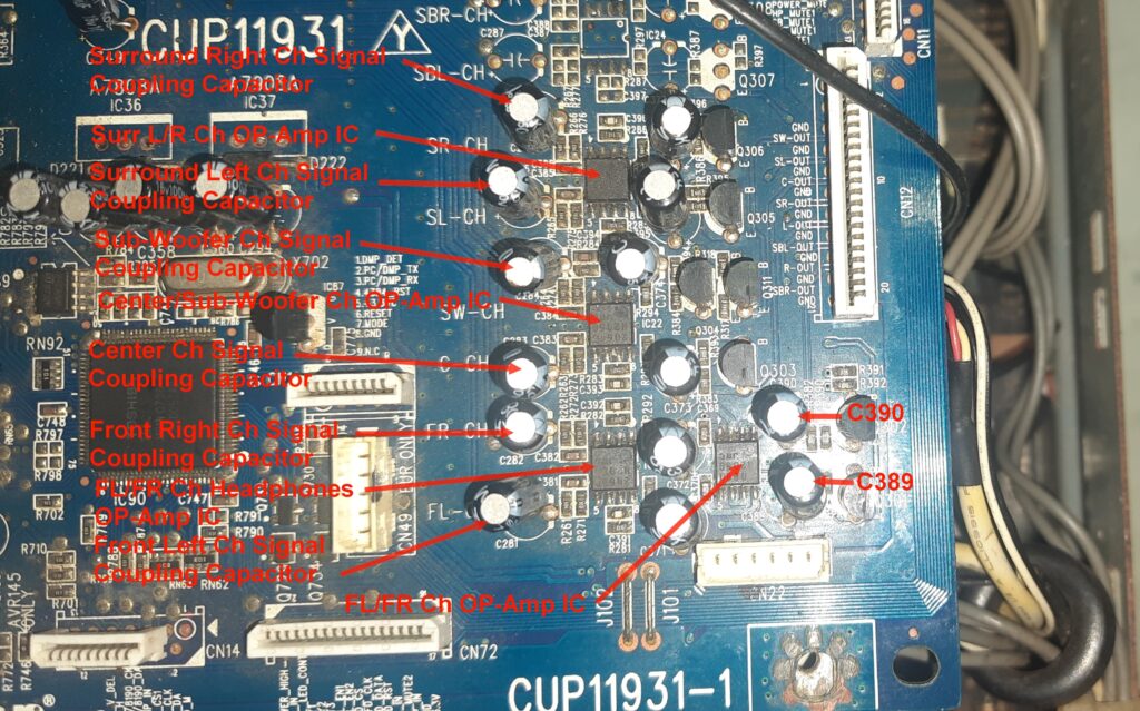
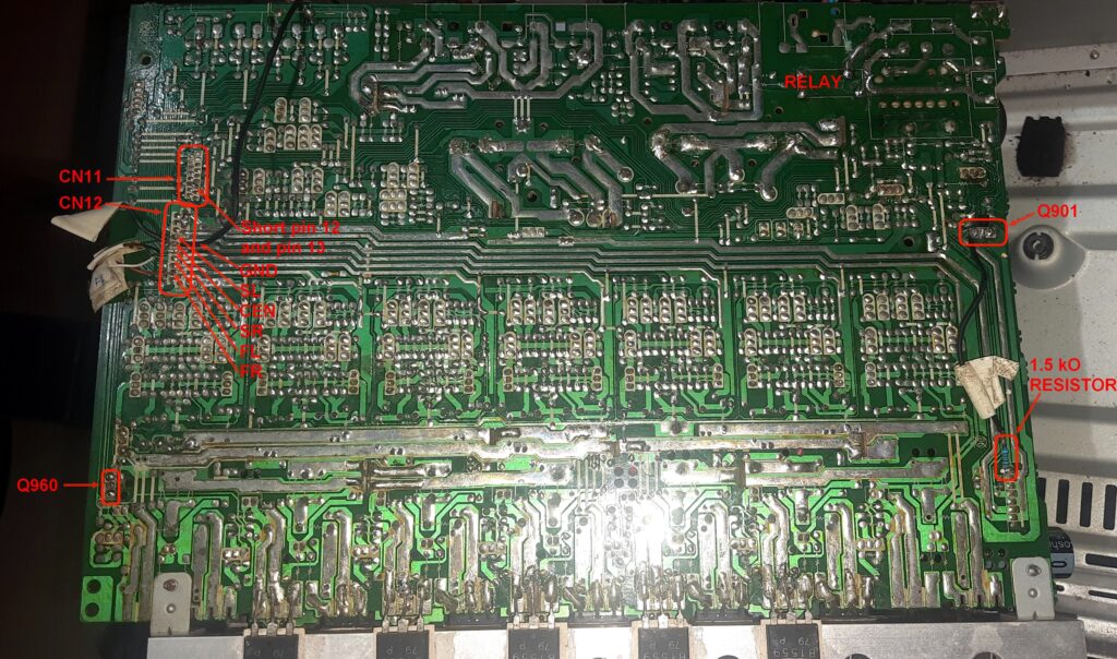
Figure 1.3: Main Power Amplifier Circuit Board – Back View
- If the amber light or standby light is on as in my amp’s case, +5V should be present. Remove the top cover. Make sure that the power cable is unplugged from the mains to avoid electric shock. Clean the inside of the amp with a paint brush and use a blower to blow out dust particles. Proceed to step 2. Otherwise, if no amber light or no standby power, check the fuse. If the fuse is ok, IC89 L7805 CP, +5V DC voltage regulator could be open and needs to be replaced. IC89 is located on the vertical regulator board near the main power transformer inserted to the main power board. The fuse is located at the main power amp board near the power relay (refer to figure 1.1 below). Proceed to step 3 to access the fuse.
- Disconnect the flat flex cable connector CN12 and CN11 (refer Figure 1.2 above) and spray the terminals with a non-conductive electronic cleaning spray. Reconnect CN12 and CN11, connect the power cord to the mains, set the standby switch to on and press the power button. Sometimes, loose contacts in CN12 and CN11 can cause the amp not to power on. CN12 carries the power on signal data to the SMD (Surface Mounted Device) IC90 a flash microcontroller unit (U-COM) that controls power on/off, power mute, remote control and many other switching functions. CN11 carries the power mute, power high and power down signal data from IC90 that triggers the relay on and off. Note that even if CN11 is disconnected, the system on blue light indicator should turn on after pressing the power button if IC90 is working, though the power relay will not be activated. In my case, the blue light didn’t turn on. So, I suspected that IC90 is defective. Proceed to step 3, skip step 4 and proceed to step 5.
- First, disconnect the power cord from the mains then remove all screws at the sides and back of the AVR. Remove the top cover first. Detach the video board, the tuner board, and the audio input board to access the main power amp board mounting screw under the audio input board.
- Check the fuse. If the fuse is busted, replace it. Re-install the audio input board and re-connect all connectors on the board. Don’t re-install the video and tuner board yet. Try powering on again. If the amp powers on, connect all speakers. Connect a suitable audio source i.e. DVD player with both coaxial/optical and analog output sources. Test all inputs one by one while also testing for sound output on all surround modes. If everything is good and you hear the usual sound when the unit was good, then problem solved. Otherwise, if still no blue light and no power, proceed to the next step.
- Most of the main power amp board mounting screws are easily accessible including the screws attaching the heat sink to unit’s bottom chassis except for one that is under the audio input board. Remove those screws and tilt the main power amp board vertically on the left side to see the back side. Locate switching transistor Q901 and pin no. 8 of CN98 at the bottom of the inserted vertical regulator board. Pin no. 8 carry’s the standby +5V DC voltage. Disconnect CN11 if connected then connect a 1.5k Ohms resistor from pin no. 8 to the base of Q901 to trigger the relay to engage or activate. The signal voltage applied to the base of Q901 from the standby +5V DC voltage effectively replaces the power_high signal voltage from IC90 (U-COM) in the audio input board (refer to Figure1. 3).
- Plug the power cord to the mains and press the standby switch. The relay should now activate. With the audio input board in place, check for +12V and -12V at the terminals of CN20. If +12V is not present, replace voltage regulator IC90. If -12V is not present as in my case, replace voltage regulator IC91. Both regulators can be found on the vertical regulator board inserted at the bottom to CN98 of the main power amp board.
- First, disconnect the power cord from the mains then remove all screws at the sides and back of the AVR. Remove the top cover first. Detach the video board, the tuner board, and the audio input board to access the main power amp board mounting screw under the audio input board.Check for overheating ICs and regulators by touch. In my case, after replacing the IC91, I noted that IC20, IC36, and IC37 are all overheating immediately after pressing the standby switch to on. I tested pressing the power button and got a momentary system-on blue light and front display that quickly disappear. IC36 and IC37 are voltage regulators that supply -7V and +7V DC to power IC20 which is the input microprocessor and controller for Dolby, DTS, and DSP surround modes. There is a very probable internal short in IC20 so I disconnected and removed both IC36 and IC37 voltage regulators onboard to cut the supply to IC20. Tested powering on but no luck. It seems that IC36 and IC37, and IC20 needs to be working fine to power the amp on, though the relationship is unclear since IC20 has a dedicated -7V and +7V regulated power supply and IC90 (U-Comm) has a +3.3V DC supply independent from IC36 and IC37 (refer to Figure 1.3).
- So, in this case the audio input board is useless and the best thing that to do is try to make the main pre-amp and main amplifier circuit working by triggering the relay to switch on as I did in step 5. Then create a 6 channel direct external audio signal input connection to the pre-amp as a last resort to salvage the unit instead of throwing it away or letting it decay.
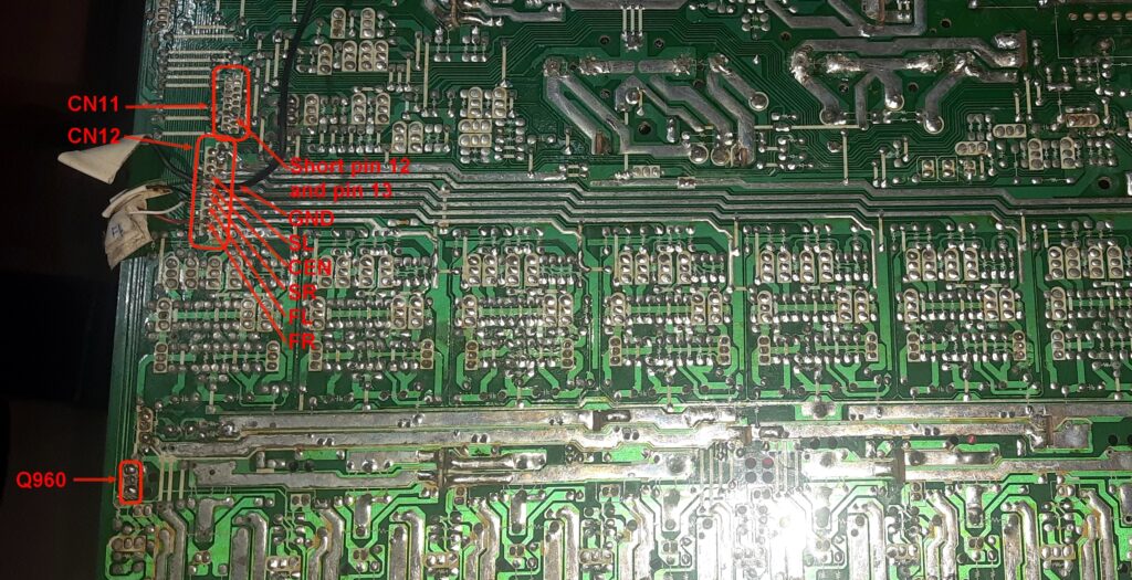
- There is another very important step to do since the power high, and power mute signal voltage from the audio input board are not present. The power high signal voltage triggers the relay to engage while the power mute signal voltage switches the biasing circuit of the main power amplifier on or off. Power mute default is on which means that the main amp even if power is present won’t work because there is no bias voltage. Power mute needs to be turned off by applying a signal voltage to the base of switching transistor Q960, a small epitaxial planar npn transistor. The base of Q960 is connected to pin 13 labeled P_M just beside pin 12 labeled power_high on connector CN11 that connects to the audio input board. Short pin 12 and pin 13 by soldering together. This way, the replaced power high signal voltage from the base of Q901 as mentioned earlier in step 5 switch off power mute while switching the bias circuit on (refer to Figure1.3).
- While the main power amp board is still tilted vertically on its left side, connect at least one speaker, connect the power cord to the mains then press the standby switch to on. Test audio by touching the terminals of CN12. You should hear a loud hum, which means that the main power amp and the pre-amp are working. Based on online data, the pre-amp and the main power module of Harman Kardon AVR 132 are not prone to failure.
Section 2: Repurposing the Amplifier
Now that the pre-amp and main power amp are working the next step is to connect the external input signals for Front Left, Front Right, Center, Sub-Woofer, Surround Left, and Surround Right channels to the pre-amp. We need the following materials for this activity:
- 3 x 2 kΩ dual channel volume control/potentiometer
- 3 x volume control knobs
- 1 m x 6 core signal cable or 6 x 1m multi-colored individual signal cable
- 6 channel RCA audio input board
- Masking tape and pen for labeling the signal cable
- Any external 6 channel surround decoder similar to the one below:
Figure 1.4: Digital Surround Sound Decoder
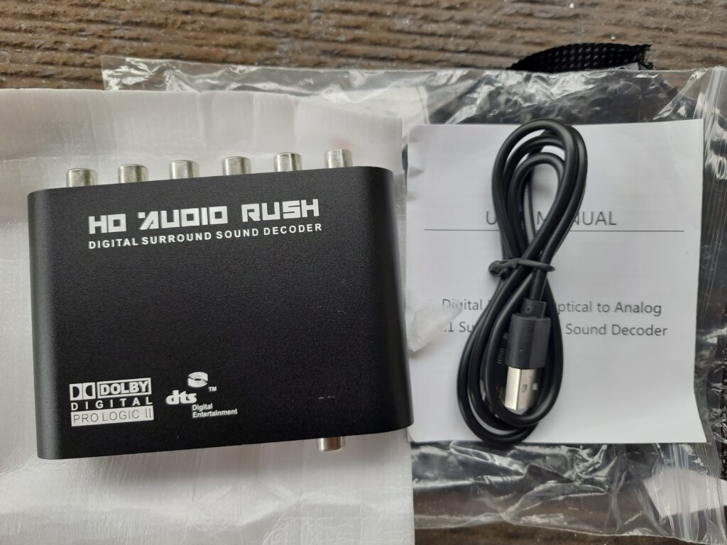
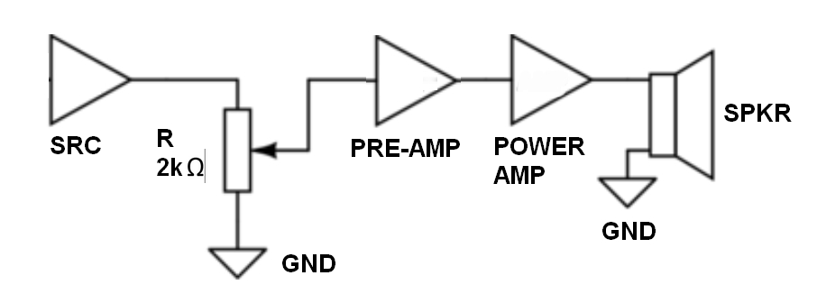
Note that we can’t use the existing rotary type volume control/potentiometer because it is for digital and not for analog control. Before you start, be guided by the block/schematic diagram shown below for the signal cable connections to the volume controls/potentiometers.
Figure 1.5: Potentiometer Block Diagram
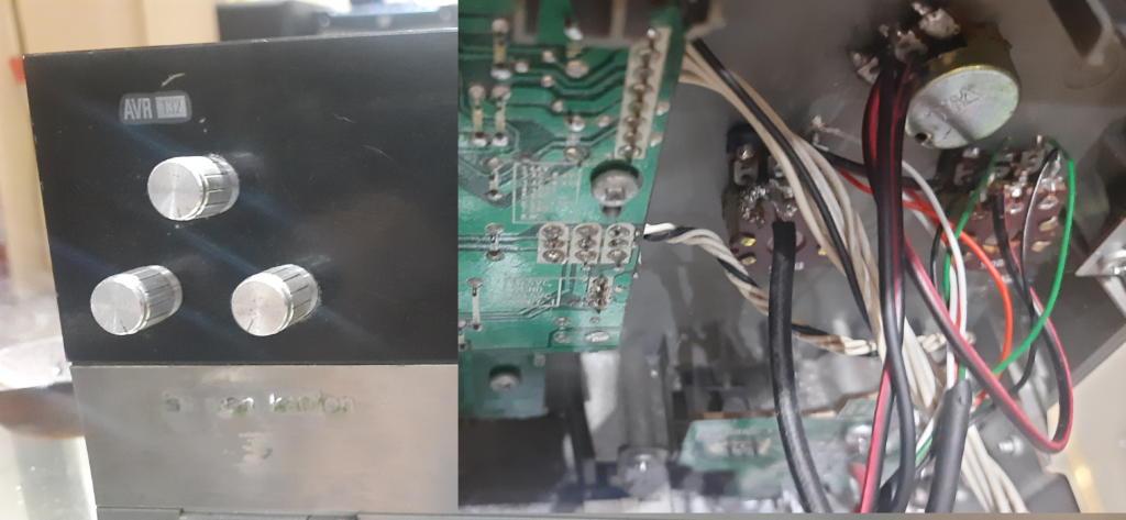
Bore suitable holes through the front panel and install the potentiometers and connect the signal cables accordingly.Figure 1.6: New Potentiometers
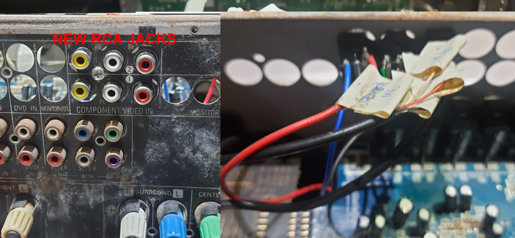
At the empty slots for video input jacks at the back panel, install the new set of 6 channel RCA input jacks and connect the signal cables accordingly. Existing RCA input jacks maybe used but I preferred to install a new set of 6 channel input jacks to avoid signal attenuation if there are shorts in the input circuit.
Figure1. 7: New RCA Female Input Jacks
There are two options for the signal input connection to the pre-amp with. Both options have pros and cons:
Option 1: Connect the signal wires except for the subwoofer to the pre-amp as shown in the image below. Disconnect all connectors in the audio input board. We don’t need any of those. Pros and cons are listed below:
Pros:
- Stable audio signal with no noticeable degradation in performance.
- No risk of DC voltage leaks to the main power amp transistors and speaker terminals that can be introduced into the main power amp if either of the op-amps get shorted internally.
- Less power consumption because the regulators
Cons:
- Low audio input level but can be compensated by increasing the level of the input signal and the volume using the newly installed volume controls.
Figure 1.8: Q960, Connectors CN11 and CN12 Location
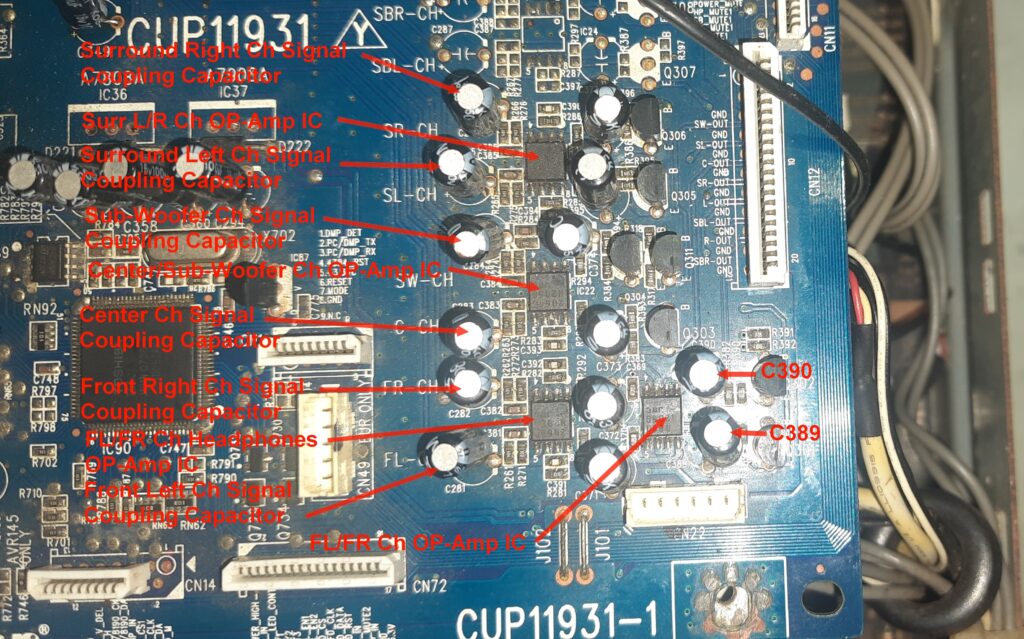
Option 2: Connect the signal wires including the subwoofer signal to the corresponding signal input coupling capacitors to the operatoinal amplifier (op-amp) ICs on the audio input board as shown in figure 1.9. Refer to figure 1.10 for the location of the op-amps. Connect CN20 and CN12 if the flat flex cable connector is not damaged yet mine was unusable so I used wires instead. Warning: Try this option at your own risk
Figure 1.9: Option 2 Suggested Connections
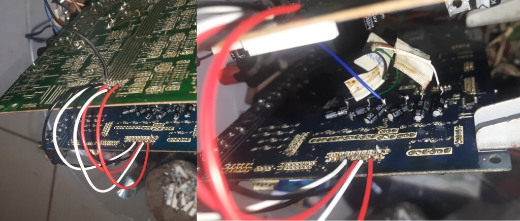
Figure 1.10: Op-amp Circuit Block Parts Labels Location
Pros and cons are listed below:
Pros:
- Better quality and very louder sound output because of additional signal processing through the op-amps. Very loud volume level can be reduced by installing lower impedance potentiometers (500 kΩ to 1000 kΩ).
Cons:
- More laborious because the coupling capacitors for each of the channels Surround Right (SR-CH), Surround Left (SL-CH), Subwoofer (SW-CH), Center (C-CH), Front Right (FR-CH), and Front Left (FL-CH) needs to be taken out from the top of the board and re-innstalled at the back of the connecting only the negative terminals to the board. The purpose is to isolate the positive terminal (signal input terminal) of the capacitors to avoid possible signal attenuation.
- Noticeable constant low frequency hum on all speakers that is not affected by volume control.
- Risk of DC voltage leaks to the main power amp transistors and speaker terminals that can be introduced into the main power amp if either of the op-amps get shorted internally.
- Risk of burning the speaker coild due to DC voltage leaks (DC offset) to the speaker terminal. The DC protector circuit may work but the system will not be able to shutdown the relay because we permanently triggered the relay to switch on everytime the unit is used.
After finishing the additional connections for any of the options that you have chosen, re-install the main amp board to the bottom of the chassis. It’s time to test the unit for validation.
Section 3: Testing and Validation
It is important to test the repurposed amplifier to ensure its functionality and performance. For this we need a 6-channels audio sources to test that all amp channels are working. Connect 6-channel signal outputs from a DVD player with 6-channels surround output or a 6-channel surround decoder output to the newly installed RCA input jacks using RCA cables. Be sure to connect an audio source to the input of the 6-channels surround decoder. For option 1, connect the subwoofer speaker box input signal directly to the source. For option 2, connect the subwoofer signal out from the DVD player/decoder to the new RCA subwoofer input jack. Connect the subwoofer out from the amp to the RCA input jack of the subwoofer speaker box.
Power on and test the sound, turning the new volume controls up or down. For option 1, the subwoofer volume control is not connected to the new volume controls. Adjust the subwoofer volume as deemed necessary using the powered subwoofer speaker box volume control. Watch a movie or two while keeping the amp open to check for any unexpected issues such as overheating of the heatsink, burning smell, and/or smoke from burning parts. If there are no issues, it’s time to re-install the tuner board though not used anymore and re-install the cover. The video audio input board needs to be out because we used the hole slots for the new RCA input jacks.
Case 1 Summary:
To sum it all up, I own a Harman Kardon AVR 132 home theatre amplifier that stopped working in 2014 due to moisture damage. Initially, I couldn’t repair or replace the audio input board, and no spare parts were available online. Recently, I decided to attempt fixing the amplifier as a DIY project, reigniting my interest in electronics. I bought two additional defective AVR132 units to see if I can fix both and referenced online tutorials and ChatGPT for guidance. Here are the detailed troubleshooting steps I followed for three different issues:
- Initial Issue: Amber light or standby light on, no display, no blue light, no power.
- Understanding the problem:
- Gather tools: soldering rod, soldering lead, tweezer, long nose plier, wire cutter/nipper, multimeter, Phillips screwdriver.
- Check the fuse and +5V DC voltage regulator IC89.
- Clean the inside of the amp and check the connectors CN72 and CN11.
- Inspect and possibly replace voltage regulators IC90 and IC91.
- Suspected that IC 20, the surround controller, and IC 90, the switching functions controller to be defective that made the audio input board useless.
- Connect a 1.5k Ω resistor from +5V standby supply to the base of the switching transistor Q901 to engage the relay to supply power to the main amplifier board.
- Short pins 12 and 13 on connector CN11 to bypass power mute.
- For repurposing, I suggested creating a 6-channel external audio input connection with the following options using new potentiometers for volume control:
- Option 1: Connect signal wires directly to the pre-amp
- Install new RCA input jacks.
- Adjust input signal levels to compensate for lower audio levels.
- Option 2: Connect signal wires through the audio input board’s operational amplifiers
- Ensure proper connections to coupling capacitors.
- Be cautious of potential low-frequency hum and DC voltage leaks.
- Monitor for overheating or other issues during testing.
Finally, I tested and validated the repurposed amplifier:
- Connect a 6-channel audio source to the new RCA input jacks.
- Test sound output and adjust volume controls.
- Monitor for any unexpected issues like overheating or burning smell.
- If everything works, reassemble the unit and enjoy the new functionality.
Conclusion:
I ended up repurposing Case 1 as a main power amplifier/booster without other functions.
Exploring similar fixing or repurposing projects can be a rewarding and innovative way to deal with electronic equipment issues. By diving into DIY repairs, you not only breathe new life into seemingly unusable devices but also unleash your creativity and problem-solving skills. Projects like these offer a unique opportunity to learn about electronics, understand intricate circuits, and discover the satisfaction of fixing something with your own hands. Whether you’re repurposing an old amplifier or tackling another electronic challenge, the journey is filled with learning, innovation, and the joy of turning the old into something functional and new. Embrace the adventure, and you might be surprised by what you can achieve!
Product References:
I’ll get a small commission if you buy the products from my links.
Digital 5.1 Audio Decoder Dts/Ac-3 Optical To 5.1-Channel RCA Analog Converter:
Buy it here: https://s.shopee.ph/7fF1j8uSBG 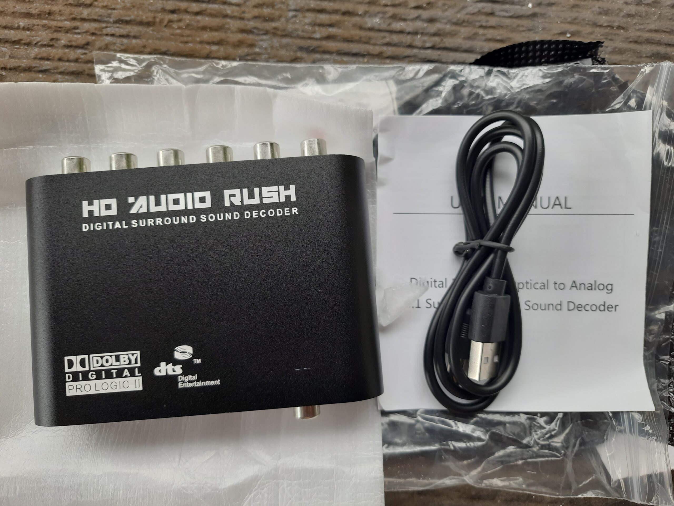
Soldering Tools Set:
Buy it here: https://s.shopee.ph/VlrChq5qW 
Hot Air Gun Soldering :
Buy it here: https://s.shopee.ph/3AmcO7oo7c 
RCA Cable Male to Male:
Buy it here: https://s.shopee.ph/40LjNsONfz 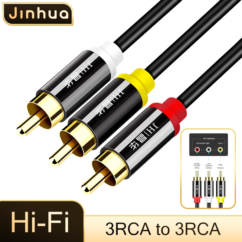
RCA Input Ports Female:
Buy it here: Buy it here: https://s.shopee.ph/A9wMjTgq3S 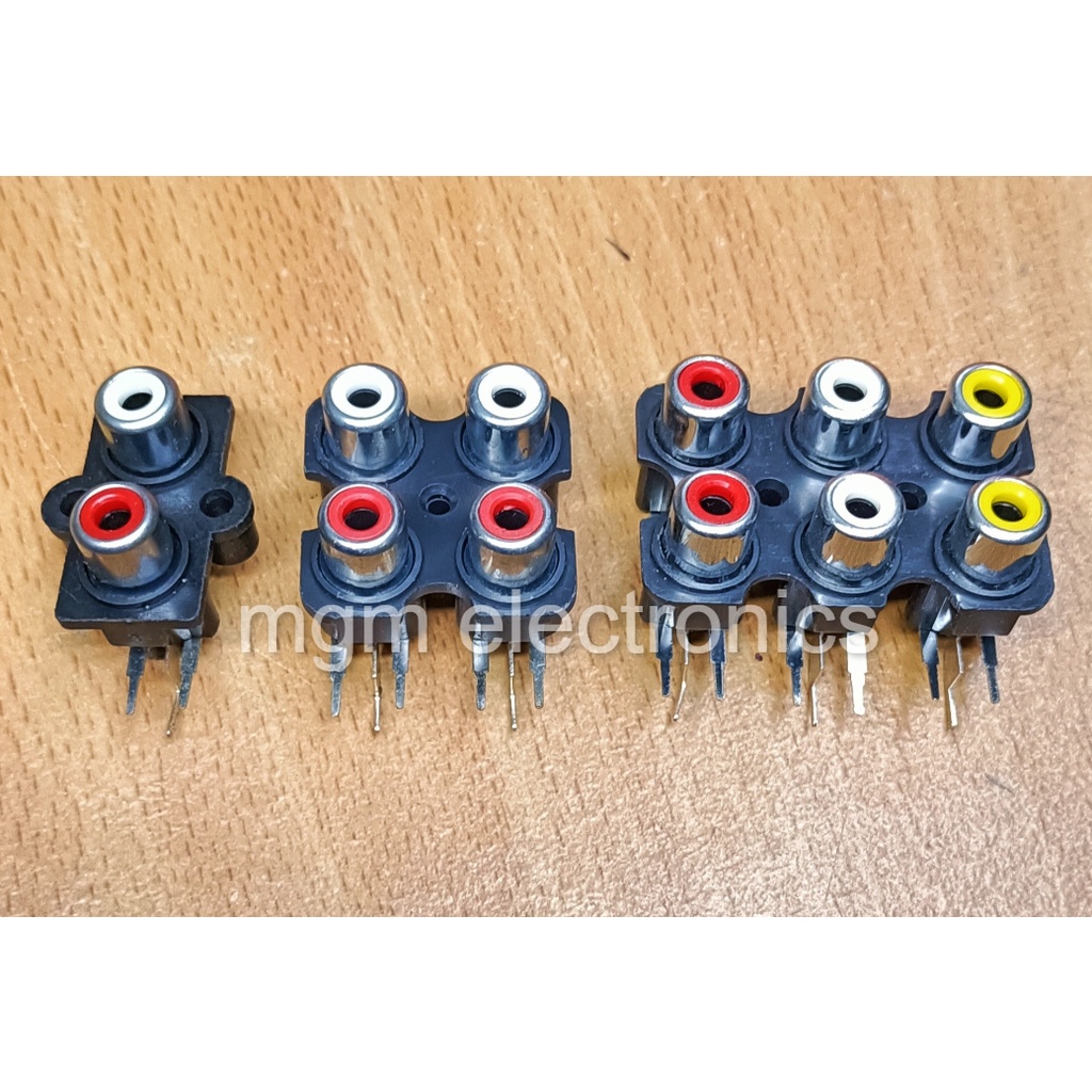
Analog Multimeter:
Buy it here: https://s.shopee.ph/2VWvd43LkB 